Yoke Assembly Diagram . phasing is the process of aligning the universal joint yokes on both ends of the drive shaft in a parallel fashion. 1pg scholar, mechanical engineering, bapurao deshmukh college of. The design of the part. to identify a flange yoke, two pieces of information are needed: a chart showing the configuration and dimensions of all slingers used on end yoke assemblies begins on page 77. design and analysis of yoke joint assembly. a universal joint in its simplest form consists of two shaft yokes at right angles to each other and a four point cross which connects the yokes.
from www.canadawideparts.com
The design of the part. phasing is the process of aligning the universal joint yokes on both ends of the drive shaft in a parallel fashion. a universal joint in its simplest form consists of two shaft yokes at right angles to each other and a four point cross which connects the yokes. a chart showing the configuration and dimensions of all slingers used on end yoke assemblies begins on page 77. design and analysis of yoke joint assembly. to identify a flange yoke, two pieces of information are needed: 1pg scholar, mechanical engineering, bapurao deshmukh college of.
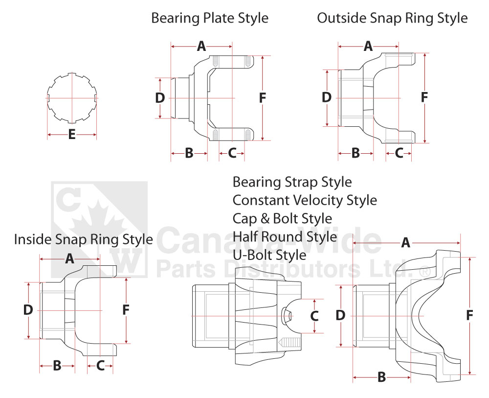
Measurement Diagrams CanadaWide Parts Distributors LTD.
Yoke Assembly Diagram a chart showing the configuration and dimensions of all slingers used on end yoke assemblies begins on page 77. 1pg scholar, mechanical engineering, bapurao deshmukh college of. design and analysis of yoke joint assembly. to identify a flange yoke, two pieces of information are needed: a chart showing the configuration and dimensions of all slingers used on end yoke assemblies begins on page 77. a universal joint in its simplest form consists of two shaft yokes at right angles to each other and a four point cross which connects the yokes. phasing is the process of aligning the universal joint yokes on both ends of the drive shaft in a parallel fashion. The design of the part.
From www.jackssmallengines.com
DR Power 48" & 60" Power Grader w/Wireless Remote (PG1) Parts Diagram Yoke Assembly Diagram a chart showing the configuration and dimensions of all slingers used on end yoke assemblies begins on page 77. a universal joint in its simplest form consists of two shaft yokes at right angles to each other and a four point cross which connects the yokes. phasing is the process of aligning the universal joint yokes on. Yoke Assembly Diagram.
From www.youtube.com
Scotch Yoke YouTube Yoke Assembly Diagram to identify a flange yoke, two pieces of information are needed: phasing is the process of aligning the universal joint yokes on both ends of the drive shaft in a parallel fashion. 1pg scholar, mechanical engineering, bapurao deshmukh college of. a universal joint in its simplest form consists of two shaft yokes at right angles to each. Yoke Assembly Diagram.
From www.researchgate.net
Diagram of Yoke, Bobbin and Base assembly part design. Download Yoke Assembly Diagram design and analysis of yoke joint assembly. phasing is the process of aligning the universal joint yokes on both ends of the drive shaft in a parallel fashion. to identify a flange yoke, two pieces of information are needed: a chart showing the configuration and dimensions of all slingers used on end yoke assemblies begins on. Yoke Assembly Diagram.
From knowledge.creamsource.com
Yoke Assembly Yoke Assembly Diagram phasing is the process of aligning the universal joint yokes on both ends of the drive shaft in a parallel fashion. a universal joint in its simplest form consists of two shaft yokes at right angles to each other and a four point cross which connects the yokes. design and analysis of yoke joint assembly. a. Yoke Assembly Diagram.
From www.researchgate.net
Diagram of Yoke, Bobbin and Base assembly part design. Download Yoke Assembly Diagram The design of the part. design and analysis of yoke joint assembly. a universal joint in its simplest form consists of two shaft yokes at right angles to each other and a four point cross which connects the yokes. phasing is the process of aligning the universal joint yokes on both ends of the drive shaft in. Yoke Assembly Diagram.
From mavink.com
Poka Yoke Diagram Yoke Assembly Diagram a universal joint in its simplest form consists of two shaft yokes at right angles to each other and a four point cross which connects the yokes. design and analysis of yoke joint assembly. The design of the part. 1pg scholar, mechanical engineering, bapurao deshmukh college of. phasing is the process of aligning the universal joint yokes. Yoke Assembly Diagram.
From avlsupply.com
ETC Balanced Yoke Assembly AVL Supply Sales Portal Yoke Assembly Diagram design and analysis of yoke joint assembly. phasing is the process of aligning the universal joint yokes on both ends of the drive shaft in a parallel fashion. The design of the part. to identify a flange yoke, two pieces of information are needed: a universal joint in its simplest form consists of two shaft yokes. Yoke Assembly Diagram.
From lmspecfab.com
PTO Yokes LM Specialty Fabrication Yoke Assembly Diagram a universal joint in its simplest form consists of two shaft yokes at right angles to each other and a four point cross which connects the yokes. 1pg scholar, mechanical engineering, bapurao deshmukh college of. The design of the part. design and analysis of yoke joint assembly. to identify a flange yoke, two pieces of information are. Yoke Assembly Diagram.
From www.peterverdone.com
SSYokeToolingAssembly Peter Verdone Designs Yoke Assembly Diagram design and analysis of yoke joint assembly. 1pg scholar, mechanical engineering, bapurao deshmukh college of. The design of the part. phasing is the process of aligning the universal joint yokes on both ends of the drive shaft in a parallel fashion. to identify a flange yoke, two pieces of information are needed: a chart showing the. Yoke Assembly Diagram.
From www.pinterest.ca
Yoke plans Oxen, Bridge building, Yoke Yoke Assembly Diagram a universal joint in its simplest form consists of two shaft yokes at right angles to each other and a four point cross which connects the yokes. The design of the part. 1pg scholar, mechanical engineering, bapurao deshmukh college of. to identify a flange yoke, two pieces of information are needed: phasing is the process of aligning. Yoke Assembly Diagram.
From www.youtube.com
Complete Scotch Yoke Mechanism Assembly YouTube Yoke Assembly Diagram The design of the part. phasing is the process of aligning the universal joint yokes on both ends of the drive shaft in a parallel fashion. a universal joint in its simplest form consists of two shaft yokes at right angles to each other and a four point cross which connects the yokes. 1pg scholar, mechanical engineering, bapurao. Yoke Assembly Diagram.
From www.multi-fab.com
Yoke Assembly MultiFab Products Yoke Assembly Diagram The design of the part. phasing is the process of aligning the universal joint yokes on both ends of the drive shaft in a parallel fashion. to identify a flange yoke, two pieces of information are needed: design and analysis of yoke joint assembly. a chart showing the configuration and dimensions of all slingers used on. Yoke Assembly Diagram.
From www.jackssmallengines.com
Troy Bilt 10056 Horse III (S/N 640000855638) Parts Diagram for Forward Yoke Assembly Diagram The design of the part. a chart showing the configuration and dimensions of all slingers used on end yoke assemblies begins on page 77. to identify a flange yoke, two pieces of information are needed: design and analysis of yoke joint assembly. 1pg scholar, mechanical engineering, bapurao deshmukh college of. phasing is the process of aligning. Yoke Assembly Diagram.
From www.autozone.com
Repair Guides Driveline Rear Driveshaft And Ujoints Yoke Assembly Diagram a universal joint in its simplest form consists of two shaft yokes at right angles to each other and a four point cross which connects the yokes. to identify a flange yoke, two pieces of information are needed: design and analysis of yoke joint assembly. 1pg scholar, mechanical engineering, bapurao deshmukh college of. phasing is the. Yoke Assembly Diagram.
From www.manualsdir.com
Slip yoke assemblies for transmission applications Spicer DRIVELINE Yoke Assembly Diagram The design of the part. to identify a flange yoke, two pieces of information are needed: 1pg scholar, mechanical engineering, bapurao deshmukh college of. phasing is the process of aligning the universal joint yokes on both ends of the drive shaft in a parallel fashion. design and analysis of yoke joint assembly. a chart showing the. Yoke Assembly Diagram.
From gwaza.co.uk
2704 PTO Yoke QR 1.3/8 6 Spline Shearbolt Assembly A5 Yoke Assembly Diagram a universal joint in its simplest form consists of two shaft yokes at right angles to each other and a four point cross which connects the yokes. The design of the part. 1pg scholar, mechanical engineering, bapurao deshmukh college of. a chart showing the configuration and dimensions of all slingers used on end yoke assemblies begins on page. Yoke Assembly Diagram.
From poonaforge.com
Yoke Shaft Assembly Poona company in Pune Yoke Assembly Diagram a chart showing the configuration and dimensions of all slingers used on end yoke assemblies begins on page 77. 1pg scholar, mechanical engineering, bapurao deshmukh college of. phasing is the process of aligning the universal joint yokes on both ends of the drive shaft in a parallel fashion. a universal joint in its simplest form consists of. Yoke Assembly Diagram.
From phlox.pro
Commercial Truck Suspension & Steering Components Slip Yoke Assembly 3 Yoke Assembly Diagram a universal joint in its simplest form consists of two shaft yokes at right angles to each other and a four point cross which connects the yokes. phasing is the process of aligning the universal joint yokes on both ends of the drive shaft in a parallel fashion. a chart showing the configuration and dimensions of all. Yoke Assembly Diagram.